Having settled on a lockdown project to take my mind off the anxiety and stress of this new reality, I started researching “quick” projects one could get stuck in. And I found a really nice page on Circuit Basics (https://www.circuitbasics.com/design-hi-fi-audio-amplifier-lm3886/) that uses the LM3886 chip amp. I think the author (Scott Campbell) has done a very good job of explaining the concepts of a chip amp, and I thank him for putting in the work on his post.
Having read the page, and then also visited the https://www.diyaudio.com/ forums, I settled on drawing the schematic in KiCad and thinking through the design in my own head to get the gist of how the LM3886 chip amp circuit works. I’ve never really done anything like this before, so it was a challenge to get to:
- Use KiCad for the first time, which was a learning curve
- Understand audio circuits
- having to think about mains electricity supply and the safety aspects involved
This all happened in May and June of 2020, the following is a write up of my experiences at each stage.
Schematic
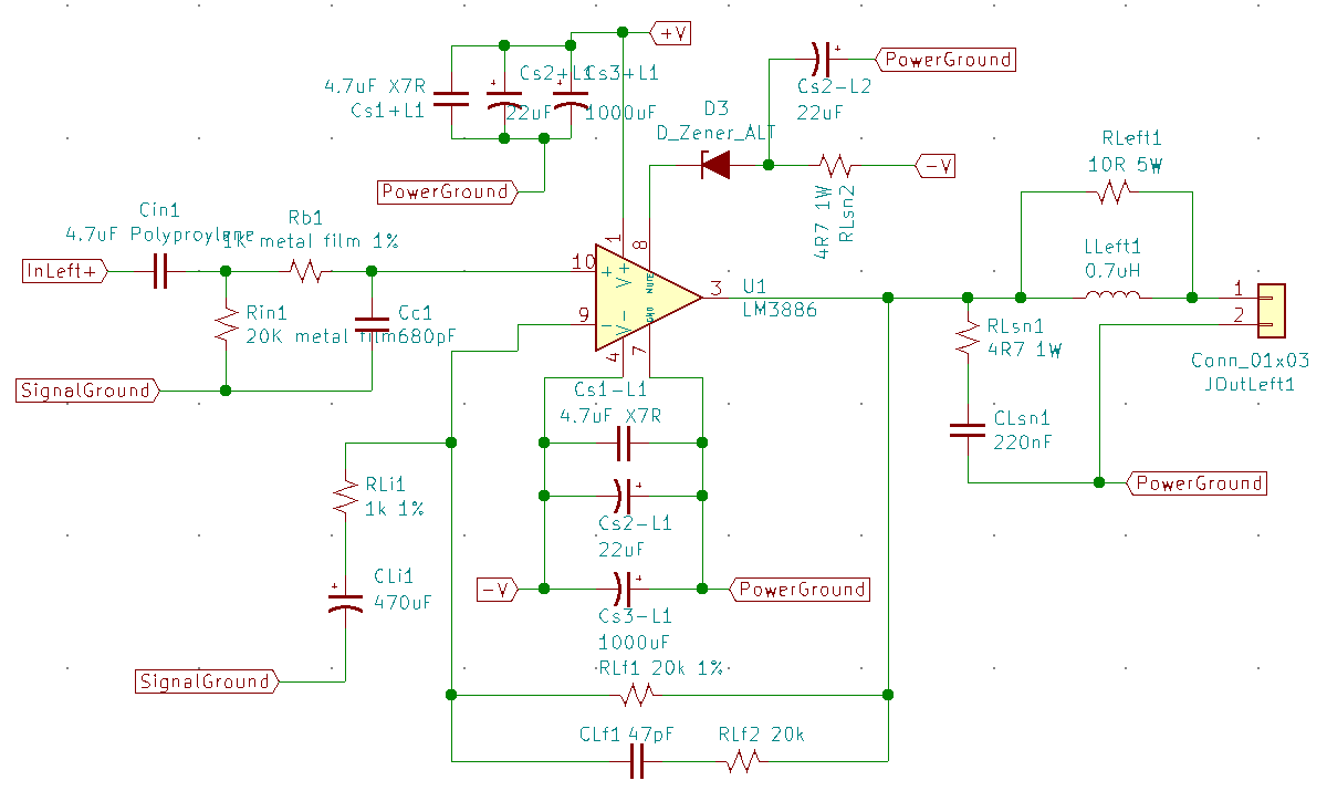
Having made the schematic that pretty much followed Scott’s schematic from Circuit Basics, this is what I had ended up with in KiCad:
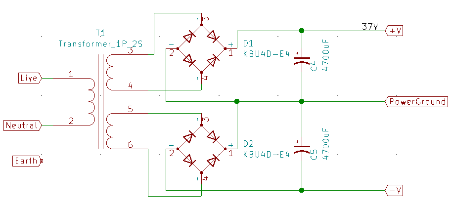
And the power supply is just a simple dual rail supply:
Parts
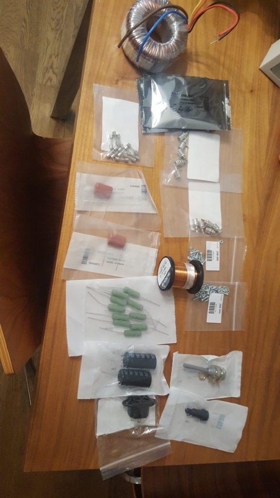
The then proceeded to order up parts that I thought was necessary for a prototype of the project. I used RS and Mouser. Here are some of the parts ordered.
Having only some stripboard to hand, I proceeded to think how I could solder the LM3886 chip to the stripboard so that all the 11 legs could fit, and I settled for a diagonal approach, where some of the tracks would have to be cut to not cause short circuits. The pins for the LM3886 can be gently coaxed slightly so that they fit into the holes just where they need to be.
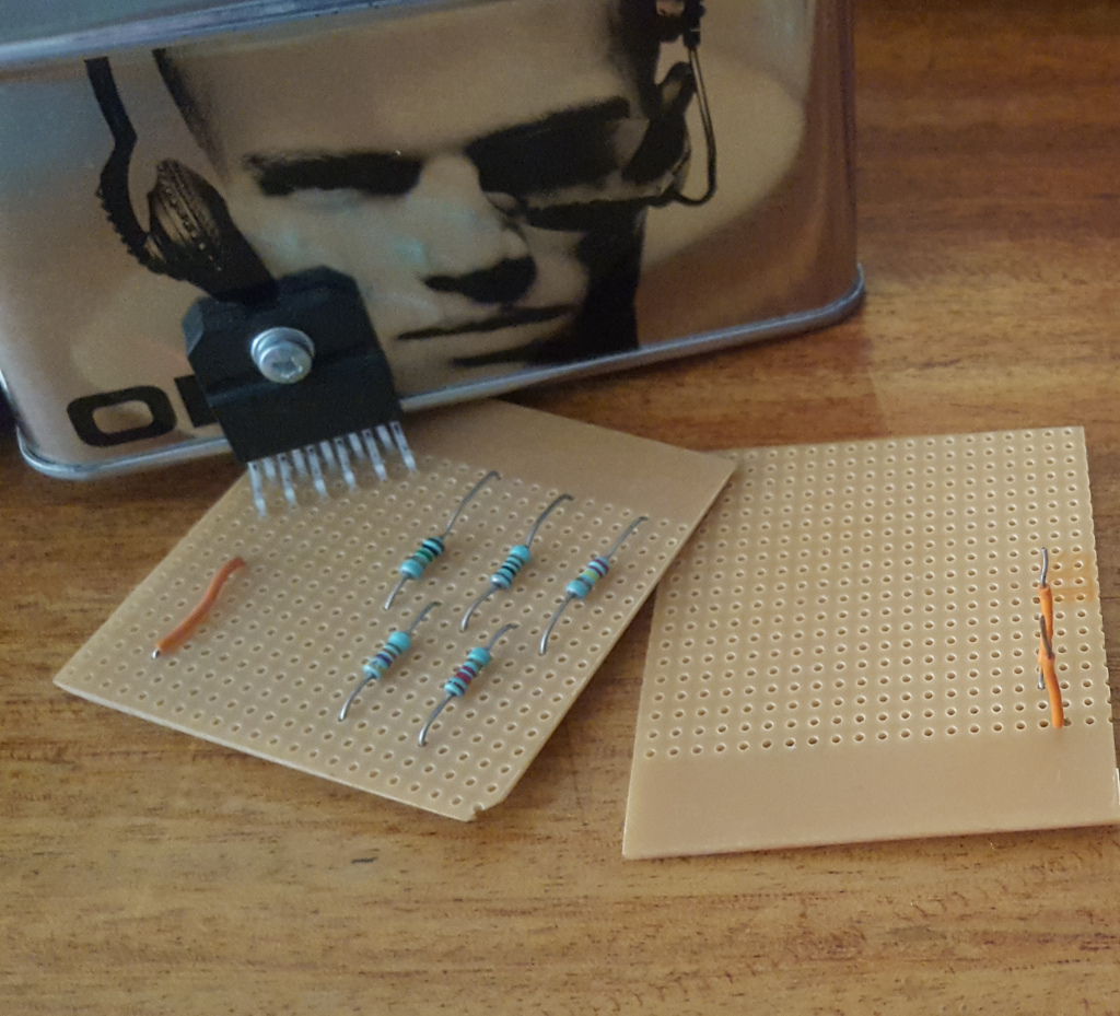
Heatsink
Having no heatsink, and suspecting the LM3886 chip would get hot, I needed some way to add extra metal to the case of the chip amp. Indeed, the datasheet for the chip amp gives guidance on the heatsink attributes required, and I knew it was going to be important to have at least something attached.
I had a coffee container that was metal and some other metal box, so I played with ways to attach. It was not easy, as the drilling process caused the metal to warp, and attachment just didn’t appear to mate perfectly for adequate heat transfer.
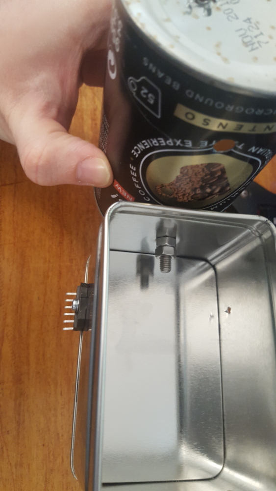
Ultimately, this heatsink was too bulky to deal with, when the circuit was outside of a box, so I decided on just a sheet of metal.
Assembly of Amp board
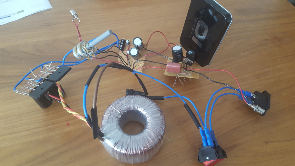
The prototype amp board with the LM3886 and the supporting components was soldered onto the strip board, and some extra capacitors and hookup wires on a second strip board.
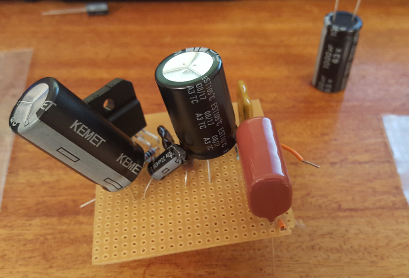
And the power supply board, soldered very badly:
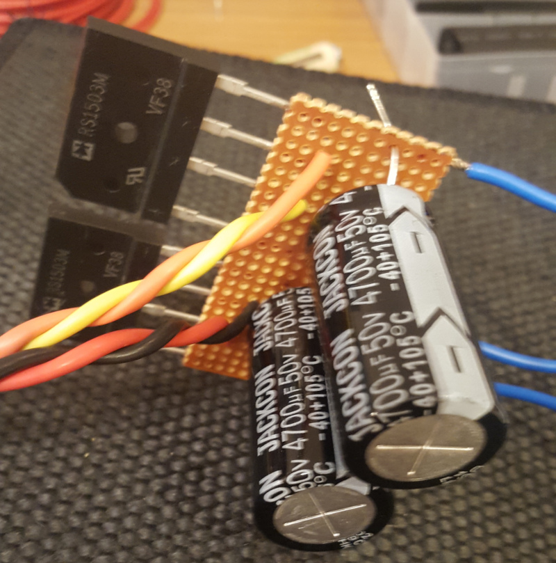
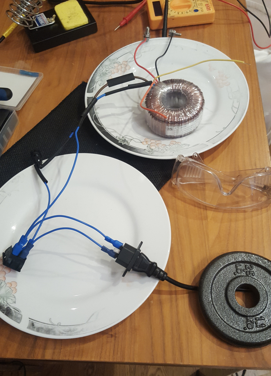
This was the first time I really experimented with mains electricity, so I was scared of things sparking or capacitors exploding. I put the mains wiring and the toroid transformer onto ceramic plates “to be more safe”. When testing, I also used a big plastic storage box to put over the circuit.
Prototype
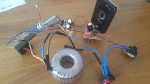
And here’s the assembled single-channel prototype:
More posts to follow.
